|
| |
Radio Voters

Voters are used to enhance the performance of any multi-channel radio system network.
In multi-channel operation, a group of independent circuits are continuously monitoring
the signal-to-noise conditions of each channel and select and assign the channel with the
best audio available at any given time.
Interfaces are available for radio operation as well as for telephone lines.
SYSTEM DESCRIPTION
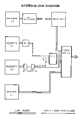
The Voting system shown on the left illustrates some of the possible ways the Voter can
be connected to the receivers.
Receiver #1 is shown to be a remote receiver, linked back to the voting site with
RF links.
This is the most common connection.The link receiver is attached directly to the voter as
if it
were a local receiver. Typically unsquelched "volume high" for audio and a
ground active COR
are used. The Link receiver should appear to the voter as if the remote receiver was
directly attached.
Receiver #2 is shown with a telephone leased line connection. This should be
ordered from your local Phone Company as a high quality, stable, equalized line. The
receiver audio and COR lines connect to the RLC (Receiver Line Card). This provides a 600
Ohm balanced driver to directly attach to your leased line. The COR from the receiver can
be positive or negative going, the RLC has a threshold adjustment and polarity jumpering
to mate with almost anything. When the COR is inactive, the RLC puts a 1950 (other
frequencies available at extra cost) carrier on the line to tell the VLC (Voter Line Card)
that there is no activity or COR. when the COR goes active, the RLC first removes the 1950
carrier and then gates the receiver audio onto the phone line. The VLC handle up to 4
receivers / telephone lines. The VLC handles the audio transition and COR detection to be
fed to the 4RV (Four Channel Receiver Voter).
Receiver #3 is shown with a microwave link. Some microwave systems can provide the
COR contact closure with its internal E+M signaling as shown in this diagram. Some may
require the RLC at the receiver to use the microwave as a phone line. We also make the MLC
(Microwave Line Card) which is the same as the VLC, but doesn't have the tone detection or
notching circuits. The MLC uses the E+M signalling for the COR input.
Receiver #4 is a local receiver at the voting site. It is connected the same as the
Link receiver shown with Receiver #1.
The VLC or MLC can coexist with direct attached receiver. The VLC also has a notch filter
that connects after the Voter to reduce the short 1950 tone burst when the COR drops. If
our mother board is used, it makes all the connections between the 4RV and VLC. The system
shown would require one DHE-R-DMP-01 (4 channel Telephone Line Rack system with 1 RLC)
which includes the Rack, Mother Board, Power Supply, VLC, 4RV, and 1 RLC. This can be
expanded later with a DHE-E-DS expansion set in increments of 4 channels. Up to 16
channels of voting can be in one rack, but the power supply will then need to be external.
The output of the voter looks like one receiver with audio and COR.
For more information, please Email novastars@the-saudi.net
| |
|